
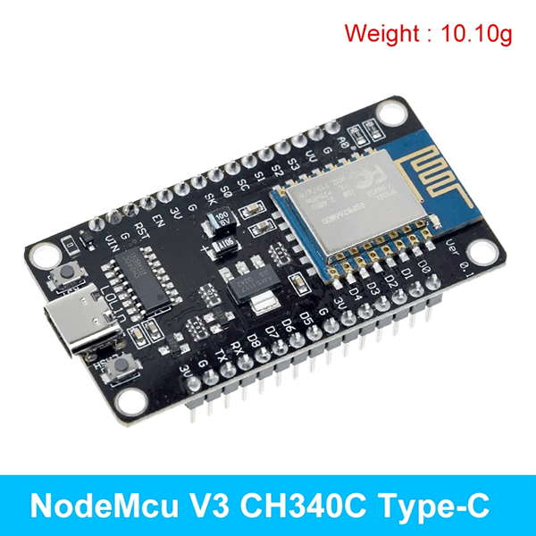
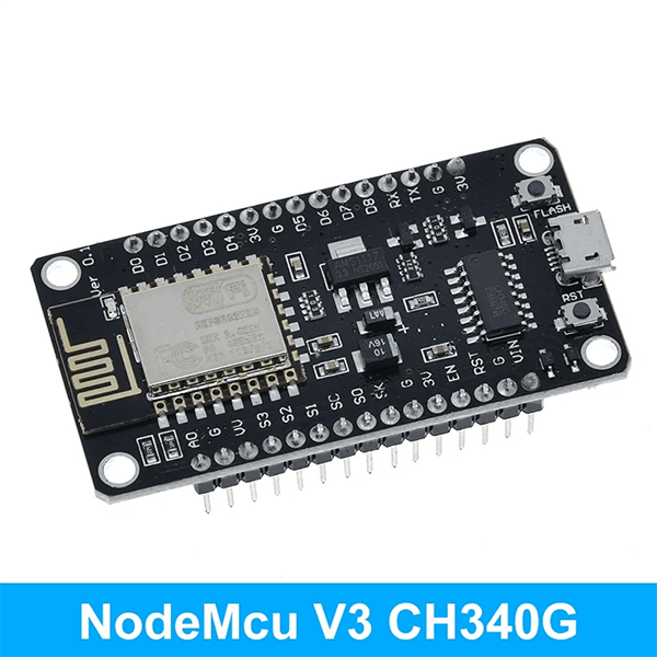
NodeMCU V3 CH340 ESP8266 Development Board with PCB Antenna
$ 54.26
Product InformationESP8266 CH340 V3 And ESP8266 CP2102InteractiveProgrammableLow costSimpleSmartWI-FI enabledArduino-like hardware IOAdvanced API for hardware I0, which can dramatically reduce the redundant work for configuring and manipulating hardware.Code like Arduino, but interactively in Lua script.Nodejs style network APIAn event-driven API for web applications that allows developers to write code running on 5mm* 5mm MCUs in Nodejs style.Greatly speed up your IOT application developing process. ESP8266 & NodeMCU Develop IntroductionThis is the tutorial to NodeMCU 1.0/2.0/2.1 development board (CP2102 / CH340 /CH9102X are applicable) and the lua programming design is given priority to.Make sure your computer have installed the USB driver ( CP2102/CH340 /CH9102X) then the device manager can find the COM .Confirm the development board has been updated for NodeMCU firmware (NodeMCU official firmware) or you can flash your it according to the fllowing guide.Part-1.Flash NodeMCU official firmware guideThe firmware given (you can choose either one of them)How to flash?Open NodeMCU-firmware-flasher, choose the firmware to flash and set the address then begin flashing. (At the same time hold RST button and FLASH button, then release RST button first while you begin flash.Release FLASH button when you see the mac-address.USB-CH340 version can flash automatically without this way).Connect NodeMCU to the computer and run flasher. Under the Config tab, configure the path of your own files.Then go back to Operation. Click Flash(F). Wait a moment.PART- 2. Use ESPlorer to test.1. Download and install ESPlorer. Supporting folder has a software with version installed Note: ESPlorer need JAVA SE 7 or above.2. Run ESPlorer, set Serial baud rate 9600. Then press the OPEN to Nodemcu connection.nodeMCU has one LED ( near the Micro USB ),We can take this LED for test. Focous on the Nodemcu schematic about this LED:LED1 is connected to GPIO16. When GPIO16 is low, LED1 will be lit. And GPIO16 is named DO on Nodemcu. First, we set GPI016 as output using “.mode” and set the level to low using “.write”. In addition, in order to be able to see the light, “tmr.delay” is used as a delay.The whole program is as follows:gpio.mode(0,gpio.OUTPUT) print(gpio.read(0),”\n”) gpio.write(0,gpio.LOW) print(gpio.read(0),”\n”) tmr.delay(1000000) gpio.write(0,gpio.HIGH) print(gpio.read(0),”\n”)3. Upload the program to Nodemcu.PART-3. Use ESP8266 LUAloader to test.Open ESP8266 LUAloader. And choose the COM, set Serial baud rate 9600,then RST. You can see the information as follow.Blue window on the right is used to test GPIO. You just need to fill in the parameter and set.Orange window on the right is used to test wifi connection. Point survey can search to the nearby WIFI services. You need to enter your user name and password to set your connection.2. You can also upload lua files to ESP8266 Lualoader which has been built in ESPlorer before. At this point, a simple test end. Enjoy yourself !
 7000 LB Double Eye Tandem Axle Suspension Kit
 7000 LB/ 8000 LB Heavy Duty Tandem Axle Slipper Suspension Kit
 7000 LB Tandem Axle Slipper Spring Hanger Kit